10 Mill Operation
This chapter will cover calculating RPM and feedrate on a milling machine, the different cutting tools used, how to dial in a milling vice, and how to tram the head of a milling machine .
Calculating and Setting Revolutions per Minute
The speed at which the cutting tool rotates is called Revolutions per Minute (RPM). Calculating RPM on a milling is similar to calculating it on a lathe. The main difference is that the cutter is rotating on a milling machine, not the workpiece. Therefore, the “D” value is the diameter of the cutting tool, not the workpiece. Like a lathe, if the RPM is set to high, it will significantly shorten the tool’s lifespan. If the RPM is set to low, the cut is not effective. The formula for setting RPM on a lathe is:
RPM = (Cutting Speed x 4) / diameter of the cutting tool
The Cutting Speed is the rate at which the tool moves in surface feet per minute (SFPM), while the diameter signifies the cutting tool size in inches.
The specific Surface Feet per Minute value varies based on factors such as the machining material and the tool used. Typically, the tool’s manufacturer provides recommendations regarding optimal cutting speed. Here are some general guidelines for cutting speed:
| Work Material (Common AISI/SAW Designations) | Highspeed Steel | Carbide |
| Tool Steel (O1) | 50 | 350 |
| Plain Steel (1010, 1012) | 90 | 360-400 |
| Alloy Steel (4140, 4150) | 80 | 350-400 |
| Aluminum (1100, 3003) | 300 | 1000 |
| Brass | 200 | 800 |
*Only use this chart as a reference, refer to tool manufacturer guidelines for accurate SFPM*
Below, is a short 7-minute video demonstrating how to set the RPM on a milling machine. Always refer to the machine’s operation manual for instructions on your specific machine.
Feedrate on a Milling Machine
The feedrate of a milling machine is typically expressed in inches per minute (in/min). This value determines the speed at which the cutter moves through a workpiece. Choosing an appropriate feedrate is crucial for achieving precise results, ensuring tool longevity, and correct surface finish.
The formula for milling machine feedrate is:
In/min= RPM x Chip load per tooth x # of teeth
RPM= The speed at which the spindle is turning
Chip load per tooth (Chip load)= The amount of material removed by each cutting tooth of the tool during each revolution (see chart below). Cutting tool manufacturers typically include the chip load on packaging.
# of teeth= The total number of cutting teeth or flutes on the milling tool.
General guidelines for chip load (always follow tool manufacturers guidelines) :
| Tool Diameter | Steel | Aluminum |
| 1/8 | 0.002-0.004” | 0.0025-0.004” |
| 1/4 | 0.0025-0.005” | 0.0025-0.005” |
| 3/8 | 0.003-0.005” | 0.0035-0.006” |
| 1/2 | 0.0035-0.006” | 0.004-0.007” |
| 3/4 | 0.0035-0.007” | 0.004-0.007” |
| 1 | 0.0035-0.0075” | 0.0045-0.007” |
Watch this 9 minute video, created by Brad Kingdon, to learn more.
Milling Cutting Tools
There are a countless number of milling cutters used in today’s machine shops. Below are some of the most common ones used:
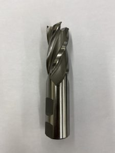
End Mills: This cutter has cutting edges at the tip and sides. End mills are versatile tools for contouring, slotting, and face milling. They come in various configurations for specific tasks, such as square end, ball end, bull end, and corner radius end mills.
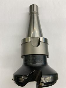
Face Mills: These cutters are suited for removing material from large, flat surfaces. They have multiple inserts for high-volume material removal. These cutters are used for squaring up and smoothing large workpieces.
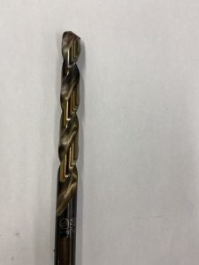
Twist Drills: Twist drills are primarily designed for drilling holes in workpieces. They feature spiral flutes that help evacuate chips while drilling.
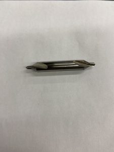
Center Drills: Center drills are used to create small starter holes in workpieces before using twist drills. Center Drills ensure accurate hole placement and drill from wandering.
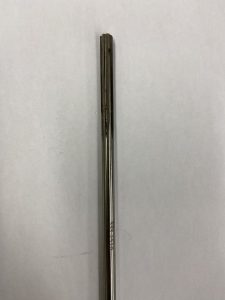
Reamers: Reamers are used for high-precision hole finishing. These tools create very accurate hole sizes and can be accurate to 0.0005″ if used properly.
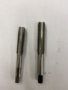
Taps: Taps are used to create threads on the inside of holes. Be aware that there are different types of taps for different operations. Below is a tapered tap (right) and bottoming tap (left). The tapered tap is used to start threads, while the bottoming tap is used to cut threads to the bottoms of holes.
Cutter Material: Milling tool cutter material is essential for tool longevity and performance. Common materials include high-speed steel (HSS) and carbide. Carbide cutters are typically favored for their hardness and ability to remove material quickly at a higher RPM and feedrate. However, this hardness comes with a trade-off, as it makes the tool brittle. This brittleness may cause the tool to chip. So, if the machining process requires a tough cutter, use a HSS one.
Below is a short 6-minute video describing different milling machine cutters and holders.
Dialing in a Milling Vice
Dialing in a milling vice is crucial for precision and accuracy on a milling machine. An adequately aligned vice results in consistent and accurate cuts. Below is a 6-minute video demonstrating how to dial in a vice on a milling machine.
Tramming in a Milling Machine
Tramming in the milling machine head is an essential maintenance task that should be completed regularly. Tramming the head ensures the milling machine head is perpendicular to the work table. Without proper tramming, the cutting tool may produce uneven surfaces, incorrect angles, tapers, or inconsistent dimensions in machined components. Below is a 12-minute video demonstrating how to tram in a milling machine.

