M. Shear Zones
Definition and geometry
Shear zones and faults
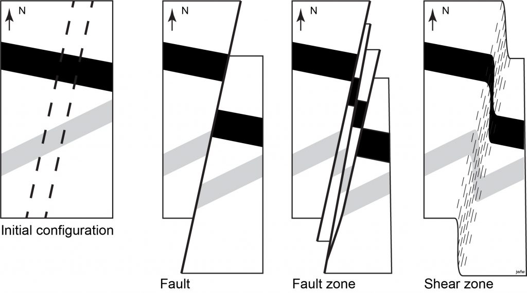
Shear zones are zones of intense ductile deformation that are thin relative their lateral extent. Shear zones, like faults, typically show offsets of older structures, but unlike faults, they lack through-going brittle fractures.
In practice, faults and shear zones are closely related. Many major structures that are faults at the Earth’s surface probably connect with ductile shear zones at depth, and in the transition it is common to find composite zones that display combinations of brittle fracture and ductile flow.
At map scale, shear zones can look just like faults, and they display all the same types of geometric relationships (offset, separation, throw, heave, etc.). We will not repeat those definitions in this section.
At outcrop and microscopic scale, though, ductile shear zones are characterized by planar and linear fabrics. Grain-size reduction is also common. When it was originally described, the metamorphic rock-type produced by this grain-size reduction was thought to be a product of brittle grinding (cataclasis) and the rock was named mylonite from a Greek word for milling flour. We now know better – the fine grain-size is the product of dynamic recrystallization – the breakdown of the original mineral grains, and growth of new, resulting from the accumulation of defects that result from extreme plastic deformation.
Shear zone kinematics
Where the kinematics of shear zones can be determined, most show a large component of rotational deformation and many turn out to have undergone progressive simple shear. However, the strain is often heterogeneous, and different parts of the shear zone show different parts of the strain history, a phenomenon known as strain partitioning.
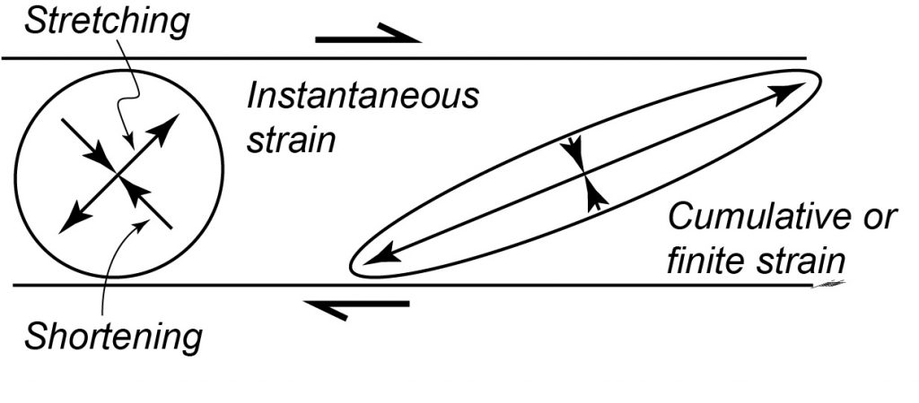
The typical geometry of a shear zone is therefore a band of heterogeneous simple shear, across which previous structures are offset.
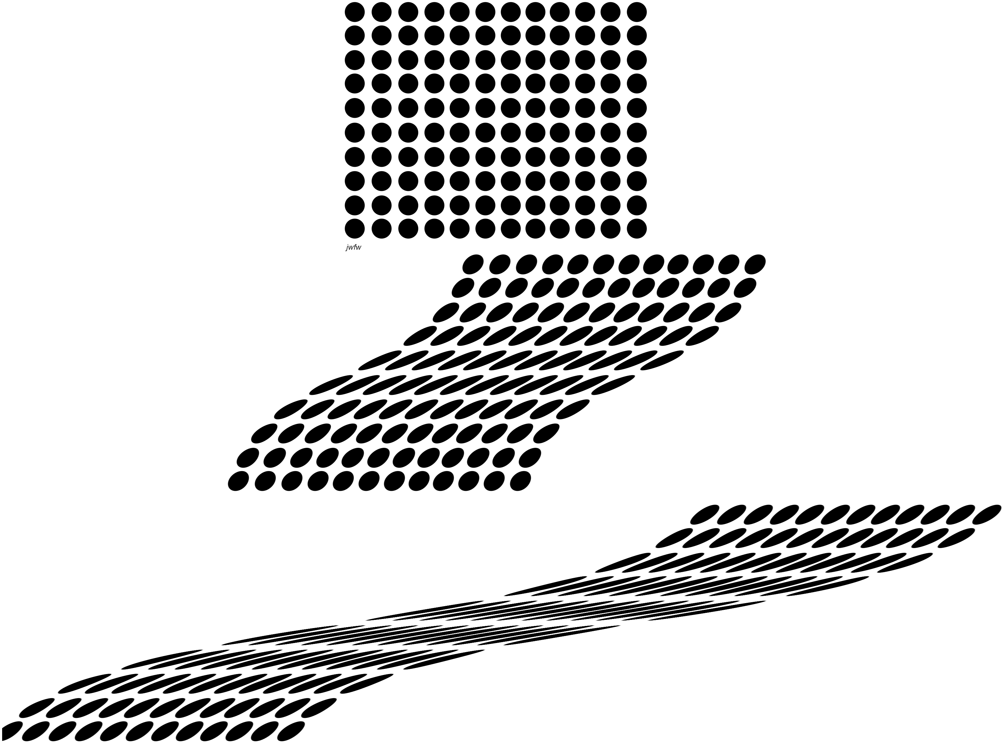
The overall strain inside a zone of ideal simple shear varies. The incremental strain typically shows strain axes at about 45° to the shear zone boundary, but the finite strain shows the effects of rotation: with increasing deformation the shape of the strain ellipse becomes more and more extreme and the extension direction (X or S1) rotates closer and closer to the shear zone boundary. Although the extension direction never quite becomes parallel to the shear zone boundary, in cases of extreme deformation, the difference in direction may be almost imperceptible.
Fabrics
Simple sigmoidal foliation patterns
The most basic pattern of foliation in a shear zone is known as sigmoidal oblique foliation. This is the fabric that is produced by the flattening of particles or domains (clasts, mineral grains, etc.)in the protolith (the original rock), when heterogeneous simple shear takes place.
In the least deformed, marginal parts of the shear zone, the foliation is weak, and oriented at around 45° to the shear zone. Towards the centre of the shear zone the foliation intensifies with increasing strain, and it curves so that it is near-parallel to the overall shear zone. The sense of rotation of the foliation with increasing strain (whether clockwise or counter-clockwise) shows the sense of shear on the zone.
Lineations
Associated with sigmoidal foliation, the stretched particles of the protolith typically are extended and define a stretching lineation which gives a streaky appearance to the foliation surface. The orientation of this lineation, when visible, and its rake in the foliation surface, are important quantities to measure in the field description of a shear zone.
C-S fabrics
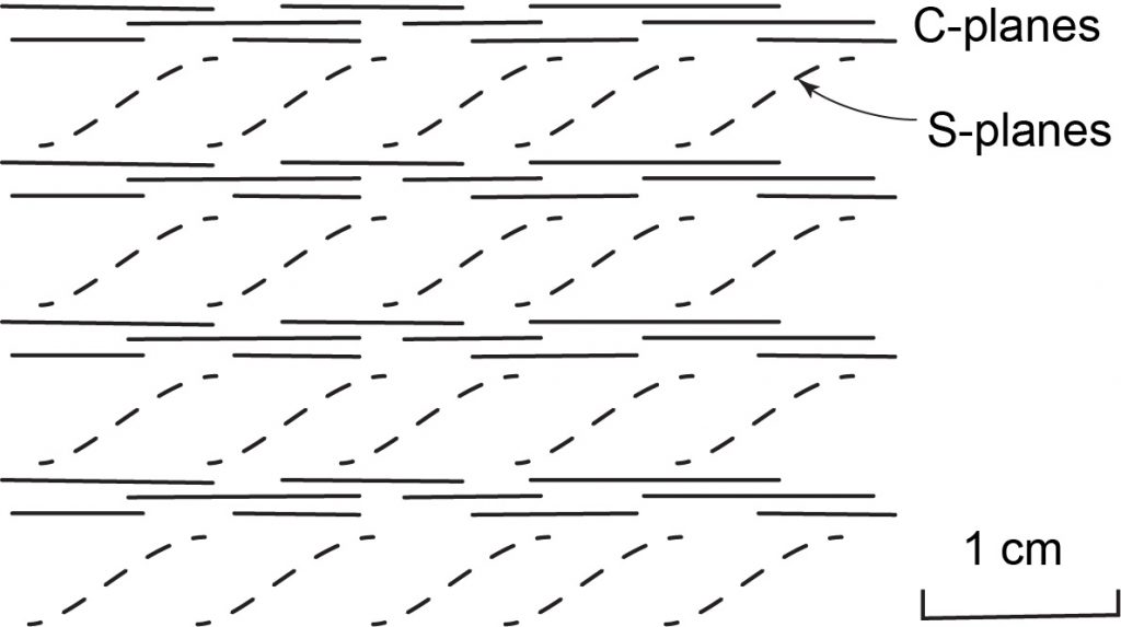
In some shear zones, strain is obviously partitioned such that zones of intense shear, and grain size reduction, alternate with zones of less intense strain, where the foliation is more oblique and the grain size is coarser. This configuration is called C-S foliation (sometimes S-C). The C-planes (where ‘C’ stands for “cisaillement” in French, meaning shearing) are the surfaces that are closer to the shear zone boundary and represent the most deformed bands. The S-planes (for “schistosité”) represent the less-deformed zones and may be oriented up to 45° from the C-planes and the shear zone boundary. The sense of rotation from S to C shows the sense of shear on the overall shear zone.
Shear bands
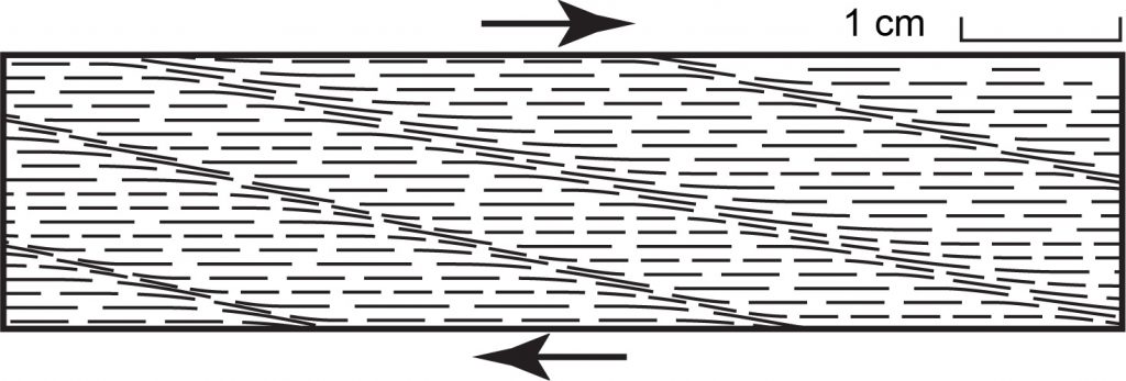
Shear band foliations are geometrically very similar to C-S foliations. They form later in the history of a shear zone, typically after a strong foliation has been developed throughout. Shear bands take the form of a new set of smaller shear zones that offset the original foliation. In a dextral shear zone they are clockwise from the original C-planes; in a sinistral shear zone the orientation is counter-clockwise. Shear bands are also known by the names “extensional crenulation cleavage” and “C-prime (C') foliation“.
Mineral structure of shear zones
It’s possible to learn what goes on in mylonite formation by looking at microscopic thin sections from shear zones. In this type of work it’s important to collect oriented rock samples. Typically this is done by marking a strike and dip symbol on a surface of the rock, before the sample is removed with a hammer. Any surface can be marked: a foliation surface or an arbitrary weathering surface. It’s important to note whether the marked surface is a top surface or an overhanging surface. As an additional check it’s useful to flag the right-hand-rule strike direction with an arrow. On a top surface, the dip direction will be clockwise from the RHR strike direction; on an overhanging surface, looking up, the dip direction will appear counter-clockwise from the RHR strike direction.
Undulose (undulatory) extinction
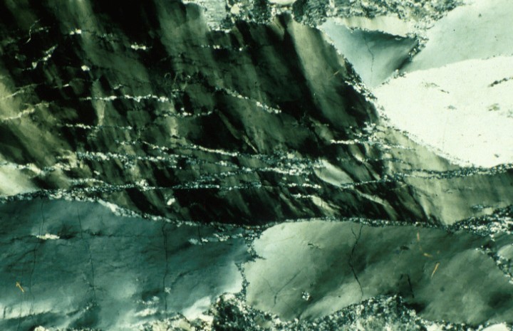
On approaching a shear zone, the first thing that is noted is an increase in the intensity of undulose (undulatory) extinction when the thin section is viewed between crossed polars. This is caused by an accumulation of defects (dislocations) in the crystal lattice.
Mortar structure
With increasing deformation, new tiny crystals appear along the grain boundaries. These are believed to form because the accumulation of dislocations makes the original crystal unstable, so solid-state recrystallization occurs producing new undeformed crystal lattices. This process is called dynamic recrystallization.
Eventually the recrystallized material surrounds the original crystals, producing what is known as mortar structure (because it looks like bricks and mortar) or core and mantle structure.
Mylonitic rocks
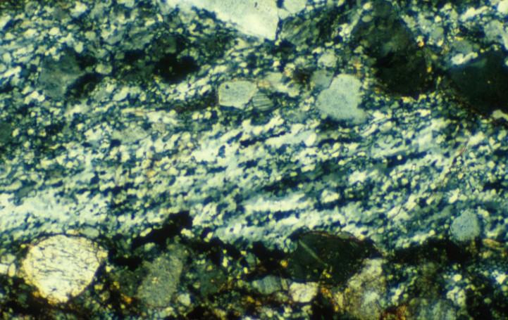
Rocks which contain significant amounts of dynamically crystallized fine-grained material are mylonitic. Mylonitic rocks are classified based on the proportion of this fine-grained material relative to remaining fragments of the original rock, known as porphyroclasts. (Don’t confuse porphyroclasts and porphyroblasts. Porphyroclasts are large grains in a metamorphic rock that are left over when the rest of the rock has had its grain size reduced by dynamic recrystallization. Porphyroblasts are large grains in a metamorphic rock that have grown in a fine-grained matrix, typically as a result of high temperature.)
- Protomylonite
If the porphyroclasts still make up more than 50% of the rock, then the rock is called a protomylonite.
- Mylonite
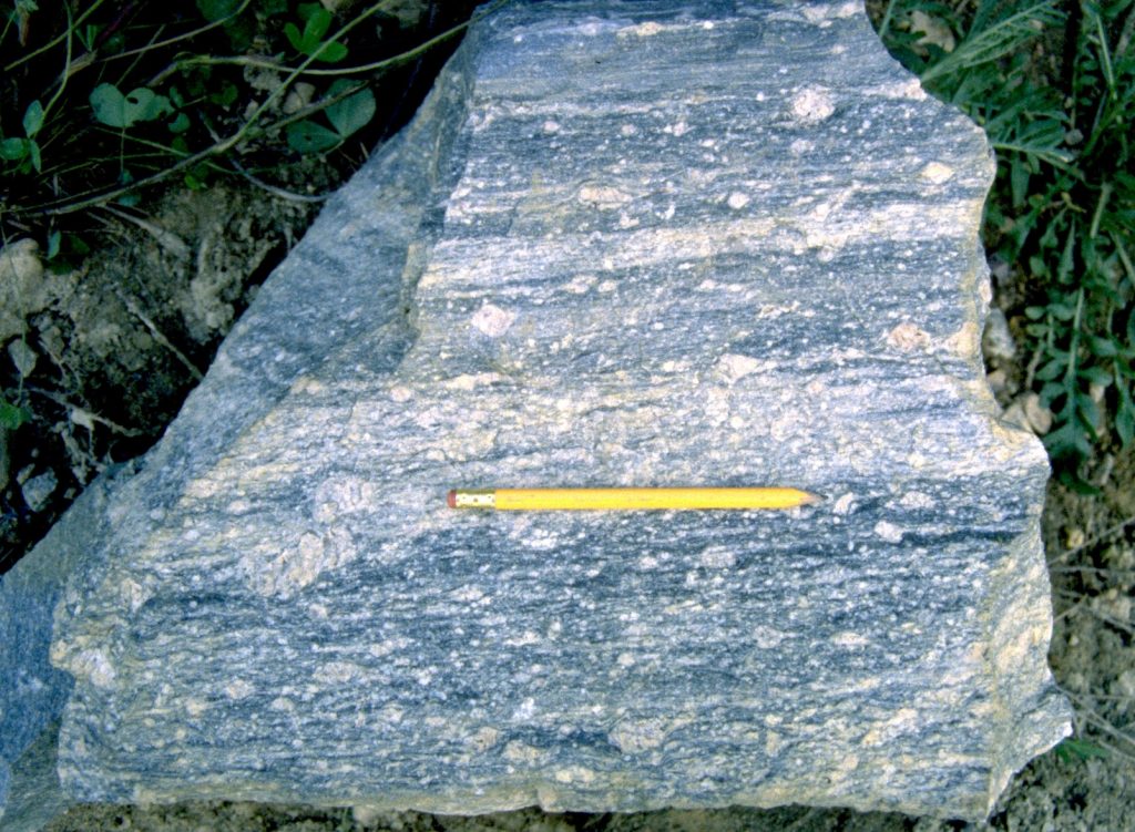
True mylonite has from 50% to 10% porphyroclasts.
- Ultramylonite
A rock which is almost entirely dynamically recrystallized, such that there are less than 10% porphyroclasts remaining, is an ultramylonite.
Matrix – porphyroclast relations
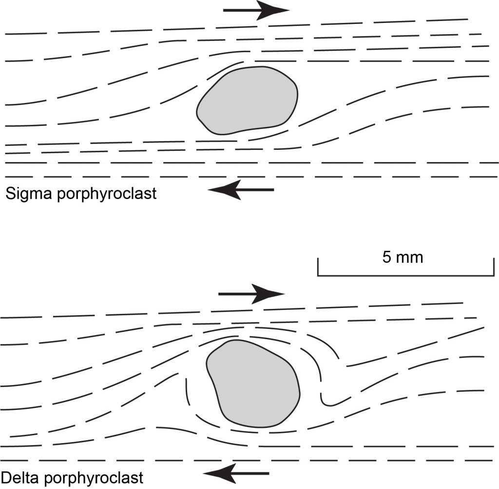
Because they are less deformed than the surrounding material, porphyroclasts represent sites of strain partitioning, and sometimes give away the sense of shear in a mylonite. There are two distinctive styles.
- Sigma structure
The foliation sweeps around a sigma porphyroclast in a somewhat rhombic shape, rather like a “small island of S-plane” in a sea of C-plane. Just like C-S fabric it can therefore indicate sense of shear. It is named after the shape of the Greek lowercase letter sigma: σ.
- Delta structure
If the porphyroclast is affected more by the rotation component of deformation, it, together with the foliation in the adjoining matrix, may be rolled together into a delta porphyroclast named for the Greek letter delta: δ.
Folds in shear zones
Asymmetric folds
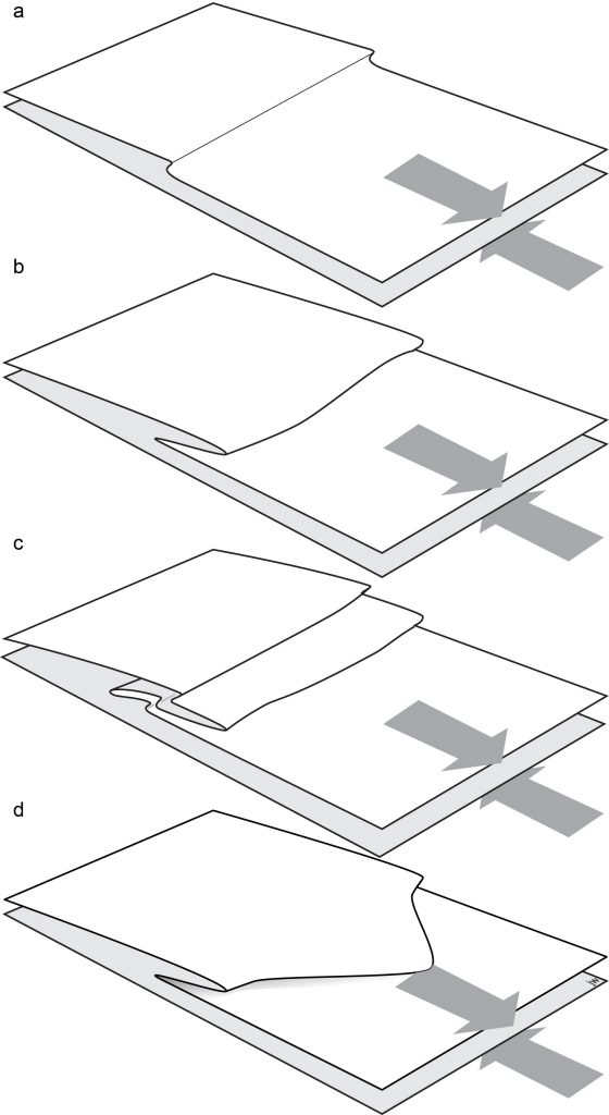
Folds in shear zones tend to form as small irregularities in the foliation are amplified by extreme strains. At first, newly developed folds show clear S or Z asymmetry, depending on whether the sense of rotation in the shear zone is counter-clockwise or clockwise from the point of view of the observer of the folds. However, the high strain typical of a well developed shear zone means that folds may easily become isoclinal, and the limbs are transposed parallel to the overall foliation, at which point the original asymmetry may be difficult to follow.
Refolded folds
Folds in shear zones tend to form as small irregularities in the foliation are amplified by extreme strains. At first, newly developed folds show clear S or Z asymmetry, depending on whether the sense of rotation in the shear zone is counter-clockwise or clockwise from the point of view of the observer of the folds. However, the high strain typical of a well developed shear zone means that folds may easily become isoclinal, and the limbs are transposed parallel to the overall foliation, at which point the original asymmetry may be difficult to follow.
Sheath folds
As folds in shear zones tighten, small irregularities on their hinges are also amplified, with the result that fold hinges may become strongly curved into geometries that resemble the finger of a glove. These are known as sheath folds, and are characteristic of highly noncoaxial deformation.
Any penetrative structure that gives a rock different properties in one direction relative to another.
Fine-grained rock formed through ductile shearing and dynamic recrystallisation in a shear zone.
Breakdown of original mineral grains and growth of new mineral grains as a result of extreme ductile deformation.
Deformation during which the strain axes have rotated.
A type of noncoaxial flow in which a single plane (the shear plane) undergoes no rotation, dilation, or distortion; typical of shear zones.
Deformation in which strain is heterogeneous and different parts of the rock show different parts of the strain history.
Strain that is not the same everywhere within a rock. Straight lines may become bent and parallel lines may becomeg non-parallel.
A type of non-coaxial deformation in which particles move along lines parallel to a single plane
Linear fabric defined by elongated domains, produced by extension.
Foliation in a shear zone characterized by intensely strained zones roughly parallel to the shear zone (C planes) and less strained zones where the foliation is oblique (S-planes).
A surface within a shear zone that is characteristically parallel to the zone boundaries and which shows the most intense deformation; from the French word "cisaillement" meaning shearing.
Foliation in a shear zone, oriented oblique to the shear zone boundary, representing less deformed regions; from the French word "schistosité".
Shear bands that form later in a history of a shear zone after a strong foliation has been developed throughout. They are typically oriented oblique to the shear zone boundaries, with the same sense of rotation (clockwise or counterclockwise) as the overall shear zone.
A linear defect in the structure of a crystal where the atoms of the crystal structure are out of alignment.
Microscopic structure characterized by rims of fine-grained recrystallised material surrounding remnants of original crystals.
A large mineral grain in a metamorphic rock that is surrounded by finer-grained material produced by grain-size reduction during deformation.
A structure formed by foliation that sweeps around a porphyroclast forming curved, rhombic shape, indicating the sense of shear.

