G. Kinematic Analysis and Strain
Everything we have done so far in this course has been about describing the ‘here and now’ of structural geology: where are structures and how are they oriented in the Earth’s crust at the present day.
To understand the origin of structures we need to know how things changed during the formation of those structures – how things moved. When we study how things moved over geologic time, we are studying kinematics.
The basic movements
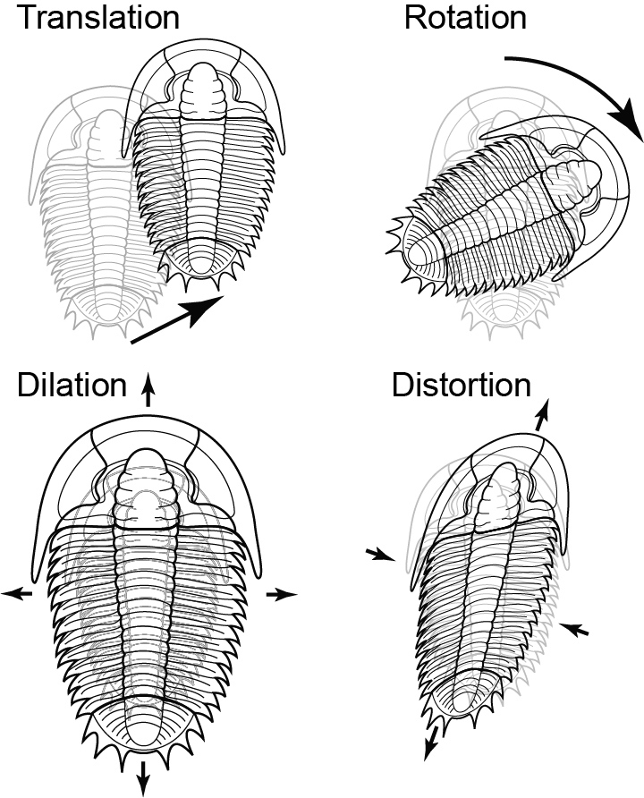
Deformation can involve 4 types of movement:
- Translation, or change in position
- Rotation or change in orientation
- Dilation or change in area or volume
- Distortion or change in shape.
The first two are rigid body deformations. The last two together constitute non-rigid deformation or strain.
Translation
Translation is measured as a displacement. Any displacement has a distance and a direction. When we look at faults we will measure the displacement of one wall of a fault relative to another. Displacement is a vector quantity.
Rotation
Rotation, or change in orientation, is typically measured in degrees, about a particular axis of rotation. (A rotation is therefore also a vector quantity, because it has a magnitude and a direction.)
A common kinematic problem involving rotation is to remove the effects of folding from some structure. For example, a sedimentologist may measure the orientation of a paleocurrent structure in folded strata, and wants to know the original direction of current flow.
This type of problem is most easily solved on the stereographic projection. As beds are ‘unfolded’, the paleocurrent directions they contain rotate along small circles on the stereonet. The small circles are centred on the fold axis.
Dilation
Volume change is very difficult to measure in real rocks. However, under some circumstances it can be quantified. Most sedimentary rocks undergo some compaction as they are buried, because pore water is expelled. Compaction results in a negative dilation. Another common phenomenon involving negative dilation is pressure solution in which some minerals in a rock are dissolved in response to stress.
Dilation is a scalar quantity – it just has a magnitude.
Distortion
Distortion is by far the most complicated type of deformation to measure. When rocks are distorted they typically get longer in some directions and shorter in others. Also, angles change in distortion. Because of this, strain cannot be represented by a scalar or a vector. It is a more complicated quantity that is called a tensor.
Strain
In popular speech the word “strain” conjours up an impression of applying force; “straining” at something implies a dynamic process. The word “strain” has a different meaning in science and engineering – it describes something purely kinematic – a change in shape or volume, however caused. There are examples of strain in which no force is involved: A reflection in a distorting mirror, and the distorted image of a basketball on a widescreen TV are both images that have undergone strain, but they are made of light rays; no force is causing the distortion.
(The corresponding dynamic term is “stress”, which we will study in a later section. Take care never to confuse stress with strain!)
All the structures we see in the Earth’s crust are manifestations of strain. Strain is such a fundamental concept in structural geology that in more advanced courses, the mathematics of strain is often treated first. In this course we take a more practical approach and focus on describing structures first. However, by now, it should be clear that changes in the shape of rocks can be recognized in all the structures you have studied so far.
Heterogeneous strain and homogeneous strain
Strain can vary from place to place in rocks. We distinguish a special case:
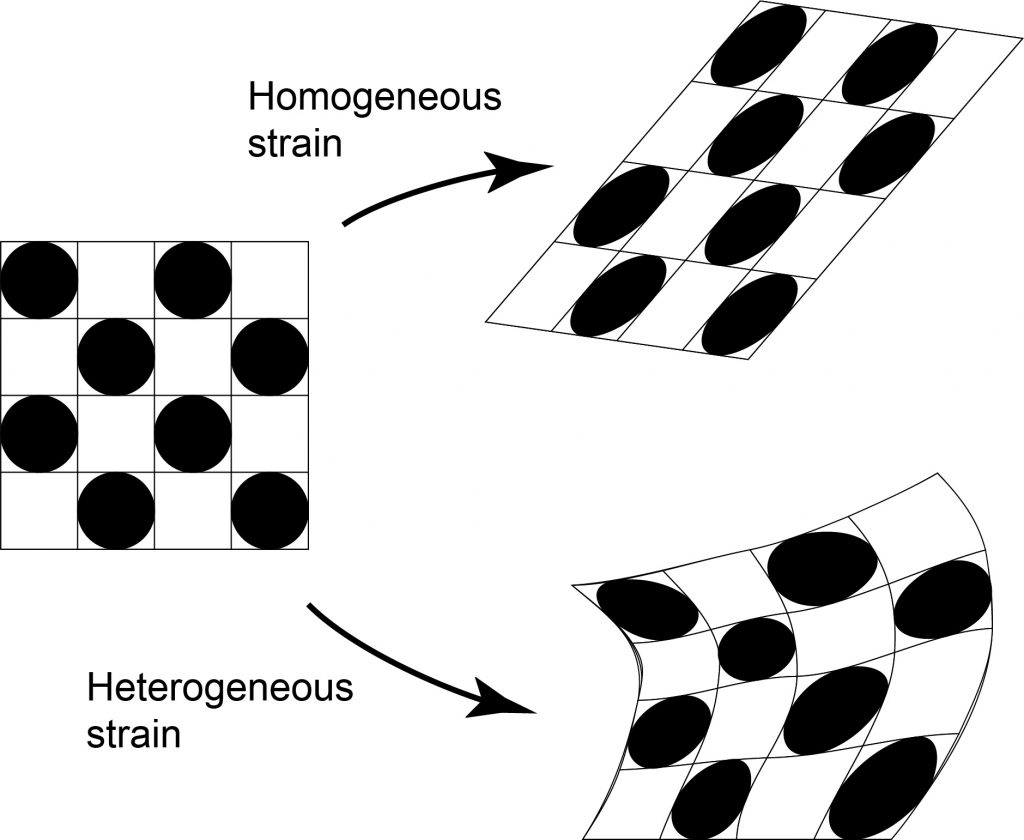
Homogenous strain: strain that is the same everywhere within a body of rock. In homogeneous strain, straight lines remain straight, parallel lines remain parallel, circles are deformed into ellipses.
Strain that is not homogeneous is heterogenous. In heterogenous strain, straight lines can be bent, and lines that were initially parallel are rotated by different amounts, becoming non-parallel.
Heterogeneous strain is difficult to deal with mathematically. However, if we look at a very small region of a heterogeneously strained rock, it can often be treated in the same way as a homogeneous strain. The strain at a point in a heterogeneously strained rock follows the same mathematical rules as homogenous strain.
Strain along lines
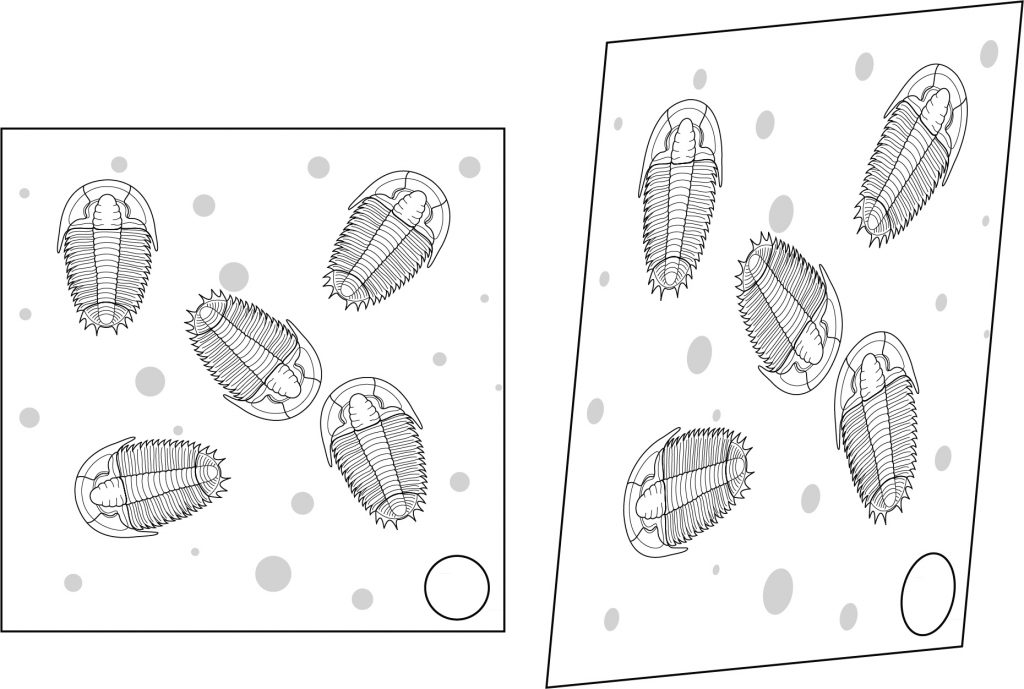
Even in a homogeneous strain, differently oriented lines experience different amounts of strain. In the diagram, each trilobite is affected differently by deformation, even though the overall strain is homogeneous.
Changes in length (longitudinal strain)
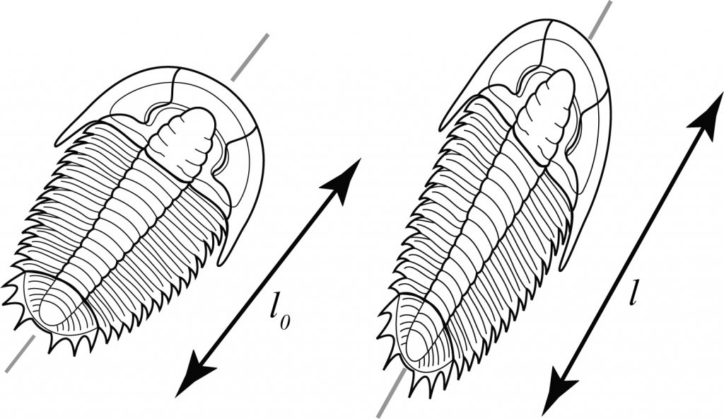
There are two ways to measure change in length. If original length is l0 and new length is l,
Extension (sometimes elongation) e = (l-l0)/l0
Extension is the fractional change in length.
Stretch s = l/l0 = 1+e
The important thing to remember is that in strained rocks the elongation varies with direction: typically some lines will have got longer and others will have got shorter.
Changes in angles (shear strain)
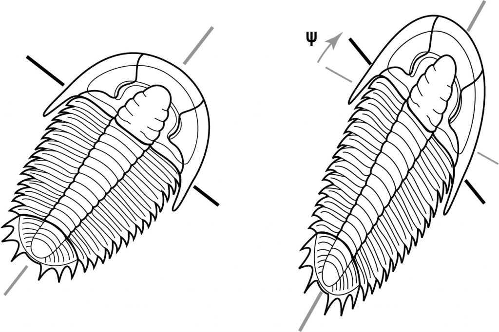
To measure change in angles we look at two lines that were originally perpendicular.
If the change in angle is ψ (psi) then
Shear strain (gamma) γ= tan ψ
There are other methods used to measure shear strain in advanced studies, so the above definition is sometimes qualified as engineering shear strain because it is the measure allegedly most used by engineers.
Shear strain also varies with direction – some lines undergo positive shear strain and some undergo negative shear strain.
In the diagram, the long axis of the trilobite has undergone positive shear strain because the line originally perpendicular to it has rotated relatively clockwise.
Strain ellipse
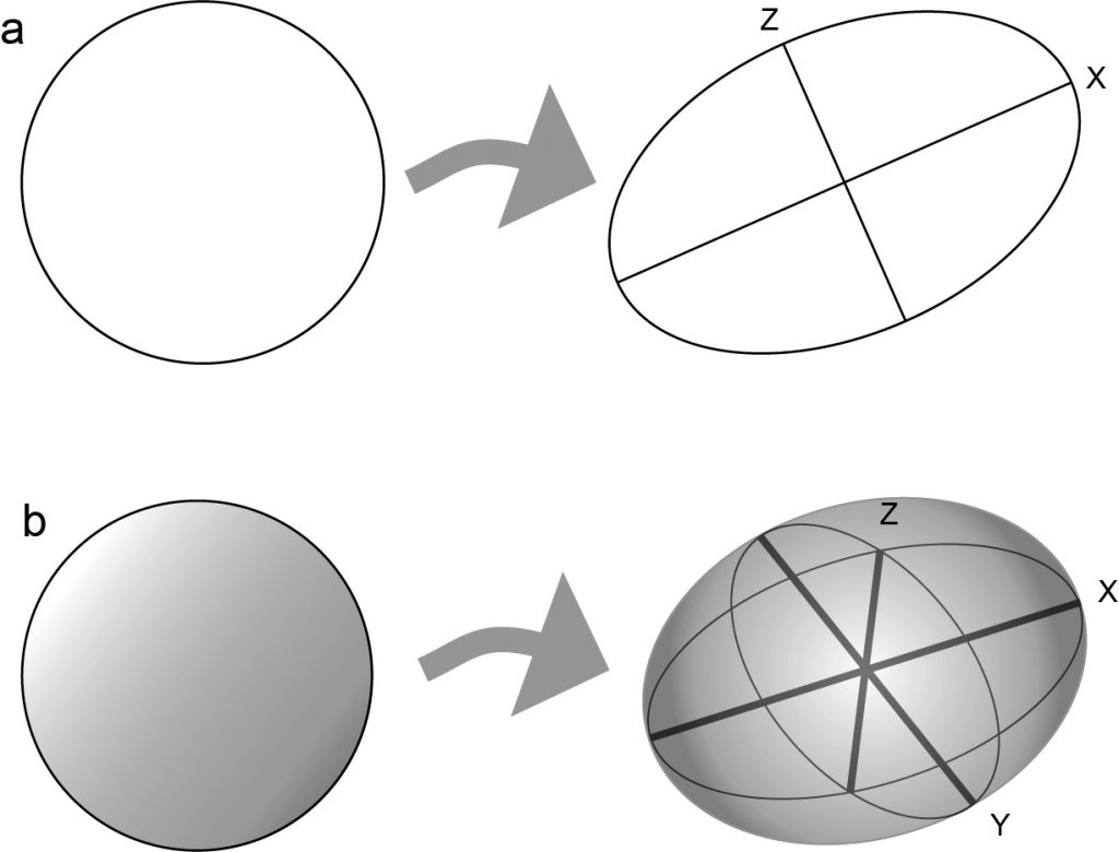
The strain ellipse is a convenient way to represent a state of homogenous strain, or the strain at a point, on a two-dimensional surface. The strain ellipse is the shape of a deformed circle that originally had unit radius.
The radius of the strain ellipse in any direction is equal to the stretch s in that direction. The strain ellipse is thus a good way to represent the variation of longitudinal strain with direction.
Strain axes
A strain ellipse has two lines that are special. They represent the maximum and minimum stretches. These lines are strain axes. (The strain axes are sometimes called X and Z. (Note: coordinate axes on a map or cross-section are sometimes x and z. Strain axes don’t necessarily coincide with any special direction on a map.)
Strain axes have some other special properties. They are always at right angles to each other, and they also represent lines of zero shear strain. This means that they were perpendicular before deformation started too. (However, during deformation they may have diverged from this perpendicular relationship and then come back to it!). The strain axes are the only lines that have this property.
The strain ratio is a convenient measure of the amount of distortion in 2-D. The strain ratio is the ratio between the long axis and the short axis of the strain ellipse:
Strain ratio RS = sX/sZ
Strain ellipsoid
The strain ellipsoid is a convenient way to represent a state of homogenous strain, or the strain at a point, in three dimensions. The strain ellipsoid is the shape of a deformed sphere that originally had unit radius.
The radius of the strain ellipsoid in any direction is equal to the stretch s in that direction. In 3-D, the strain ellipsoid is thus a good way to represent the variation of longitudinal strain with direction.
A strain ellipsoid has three lines X,Y and Z that are special. They represent the maximum and minimum stretches, called sX and sZ respectively, and a third, intermediate axis of intermediate stretch sY, that is mutually perpendicular to the other two. These lines are strain axes.
They have some other special properties. They are at right angles to each other, and they also represent poles to planes of zero shear strain. This means that they were perpendicular before deformation started too. (However, during deformation they may have diverged from this perpendicular relationship and then come back to it!). The strain axes are the only lines that have this property.
In 3D the strain axes are poles to three principal planes of strain.
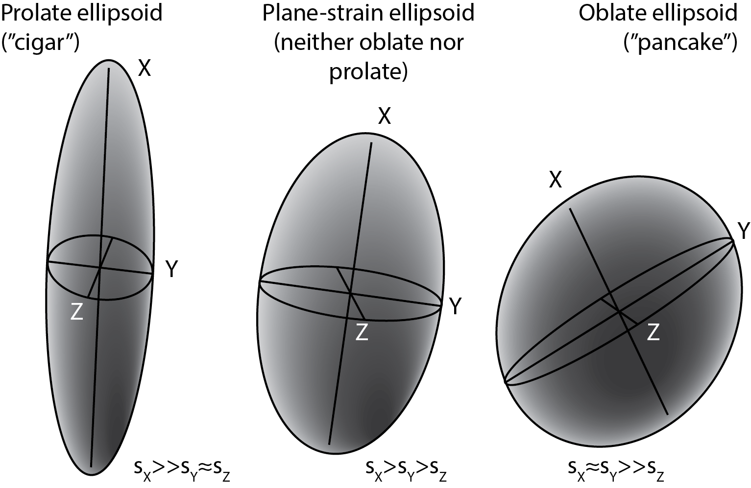
In 3D the shape of the strain ellipsoid can’t be defined by a single strain ratio. Instead we recognize two strain ratios a= sX/sY and b= sY/sZ. If a is large and b is small then the strain ellipsoid looks like a football or a cigar, and is described as prolate. Rocks with prolate strains often display strong linear fabrics (lineations). In contrast if a is small and b is large then the strain ellipsoid looks like a cushion or a pancake, and is described as oblate. Rocks with oblate strains often display strong planar fabrics (foliations).
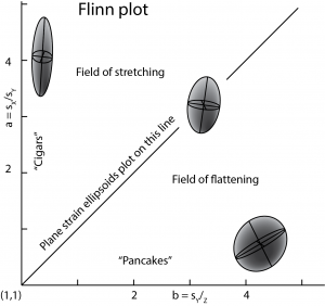
The range of possible strain ellipsoid shapes can be illustrated on a graph of a against b known as a Flinn plot.
Deformation histories
Rotational and non-rotational deformation
All the above measures have concerned just strain. However, if we look at the whole deformation picture, we may see situations where rotation has gone on at the same time as strain. Under these circumstances it’s helpful to look at the behaviour of the strain axes.
If the strain axes have the same orientation as they did before deformation started, then the deformation is non-rotational (sometimes irrotational). (Note that even in a non-rotational strain other lines will have been rotated, and will show shear strain, but it is the strain axes that are important for the terminology here.)
If the strain axes have rotated during deformation, then the deformation is described as rotational.
Finite deformation and deformation rate
Once we start looking at rotation, it’s difficult to avoid discussing strain history too. When we look at a deformed rock what we see is the product of a whole history of deformation. That end product is called the finite deformation and the strain part of the deformation is the finite strain.
In more detailed analyses of strain, we may be interested in all the tiny increments of strain that have contributed to the final picture. Each one is called an incremental strain.
The infinitesimal strain is the end product of this type of thinking. The strain history is thought of as being made up of an infinite number of infinitesimal strain increments. (The general idea should be familiar if you have taken a class in calculus.) This idea of infinitesimal strain becomes important if we look at strain rates. Strain rates are typically measured in units of per second, or s-1 sometimes expressed as strains per second. In geologically reasonable situations, the amount of strain that occurs in a second is almost infinitesimal. Typical ductile strain rates in the Earth’s crust are thought to be between 10-12 and 10-15 s-1.
Coaxial and noncoaxial deformation histories
If the strain increments are all non-rotational, then the strain axes maintain their same direction relative to the material of the rock. The deformation is called coaxial. This type of deformation is also called pure strain.
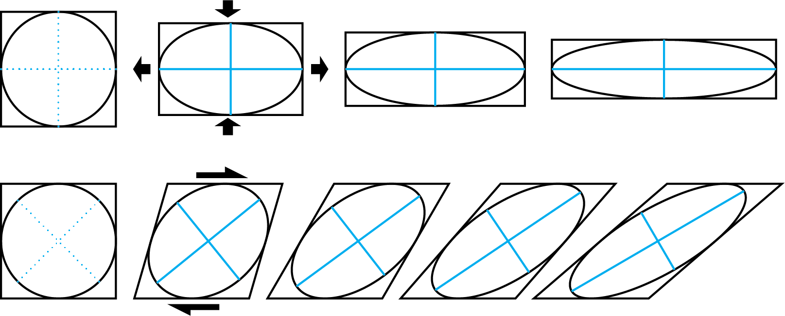
Any other type of strain history is a noncoaxial. There are many types of noncoaxial strain history, but one particular type is important in the study of shear zones. It is simple shear. In simple shear, all the particles of the rock move in the same direction, but the strain axes are progressively rotated. Sometimes, by looking in detail at the fabric of shear zones, we can distinguish the sense of rotation and figure out which way the rocks were moving.
The study of how parts of the Earth moved over geologic time. Include changes in position, orientation, size, and shape that occurred between the formation of the rocks and their present day configuration.
The movements of parts of the Earth's crust relative to each other.
Change in size and shape (dilation and distortion).
A physical quantity that has magnitude and direction, and can be represented by an arrow.
Volume loss due to the expulsion of water as rocks are buried.
A phenomenon whereby minerals in a rock are selectively dissolved in response to stress.
A physical quantity that can be represented by a single number.
A physical quantity that varies in magnitude with orientation, and can be represented by an ellipse or ellipsoid, or by a square matrix of numbers. (Strictly speaking this definition describes a 2nd-order tensor; 1st-order tensors are here referred to as vectors.)
Strain that is the same everywhere within a rock. Straight lines remains straight, parallel lines remain parallel.
Strain that is not the same everywhere within a rock. Straight lines may become bent and parallel lines may becomeg non-parallel.
The shape of a deformed circle that originally had unit radius.
Three mutually perpendicular lines in a strain ellipsoid representing the maximum, minimum, and intermediate stretches; also, the poles to three planes of zero shear strain.
The ratio between the long and short axis of the strain ellipse, a convenient measure of the amount of distortion in two dimensions.
The shape of a deformed sphere that originally had unit radius.
The shape of an ellipsoid with one axis much longer than the other two. Informally, a "cigar".
The shape of an ellipsoid with one axis much shorter than the other two. Informally, a "pancake".
The total deformation that a part of the Earth has undergone, between its original configuration and the present-day state.
The total strain that a part of the Earth has undergone, between its original configuration and the present-day state.
The strain that occurred during a small interval in the history of deformation.
The strain that was occurring a single instant during the history of deformation. (The limit of incremental deformation as the time interval tends to zero.)
Strain per unit time.
Deformation in which the strain axes remain fixed to the rock material throughout deformation
Coaxial deformation: deformation in which the rock material is not rotated relative to the strain axes.
Deformation in which the strain axes vary in orientation relative to the rock material over time.
A type of non-coaxial deformation in which particles move along lines parallel to a single plane

